Introduction
The context
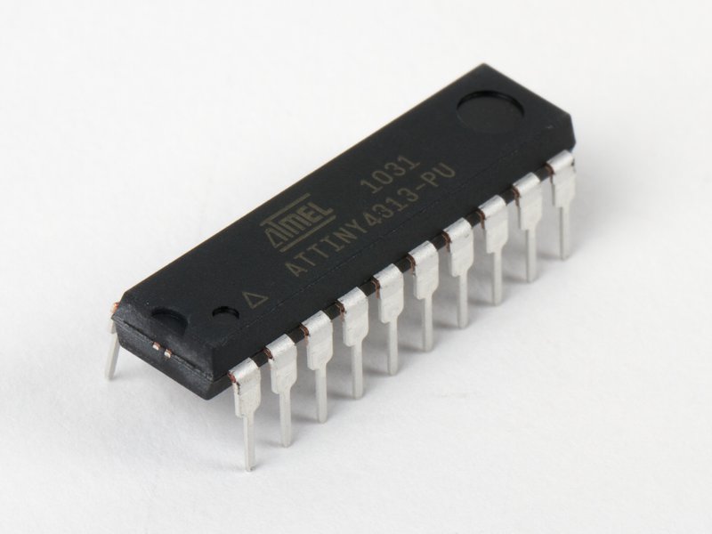
For a personal project, I want to program an Atmel ATtiny4313 microcontroller. I use microcontrollers for several years, but not on a regular basis (maybe 3-4 times a year), mostly for testing and generally with a deceptive result. But failure isn't the best training?
This article aims to share my errors and success, as well as being a personal log.
The project
The project is to replace the main board of a Soundpool MO4, a MIDI OUT extension for the Atari ST; details here.
Overall, the project is pretty simple: reading the parallel port and copy verbatim the data to MIDI out. This is the reason behind my choice of this particular microcontroller, since it embeds an USART and has an 8 bits parallel port (20 pins DIP package).
The MO4 having 4 MIDI Outs, I will use 4 ATTiny4313, one for each out; this is actually cheaper than finding a 4-channel USART. Each microcontroller must determine if the data present on the parallel port should be sent (it's for me) or dropped (not for me). Also, they must listen to the /Strobe signal; receiving 4 blinks of /Strobe within 12 micro-seconds means the program must reset. The embedded Timer 0 will be used to measure the time.
The Busy signal has two purposes: to inform the driver the interface is ready after a request to Reset, and to warn the driver the interface is currently busy.
I will add an activity LED, which is missing feature on the MO4. The LED will blink on every byte sent. However, since MIDI messages are short (a NOTE ON message is less than 1 ms), I will use Timer 1 to light up the LED for a longer period of time (~ 1/25 sec).
Finally, for the clocking, only 1 microcontroller will use a crystal; the CKOUT pin will be used to distribute the clock to the others.

In theory, this project is extensible, as far as a new driver is written to replace MO44.DRV
The environment
Here is the environment I'm using:
- Linux Ubuntu 20.04
- Arduino IDE 1.8.19 installed as snap (containerized application)
- Arduino Mini rev 5
- Arduino usb2serial board
- Breadboard
Part 1: Programming in C
Programming the Programmer
Introduction
The idea is to program the Arduino Mini to behave as an ISP, In-System Programmer, compatible with STK500. Once done, the ISP will communicate with the ATtiny via the SPI port.

Breadboard
- Place the components on the breadboard and do the wiring as follows:

Note: To have a better timing, I had to add an 8 MHz crystal between pins 4 and 5, as well as 2 * 15pF capacitors. Refer to section 6.2.5 of the ATtiny 4313 datasheet. I also added a 100nF ceramic disk decoupling capacitor between pins 10 and 20, over the chip; maybe not strictly required, but at least it couldn't harm.

Loading ISP
- Start Arduino IDE
- Select the board (in my case Arduino Mini):
Tools → Board: → Arduino AVR boards → Arduino Mini - Select the programmer (in my case AVR ISP mkII):
Tools → Programmer: → AVRISP mkII - Load the sketch:
File → Examples → 11.ArduinoISP → ArduinoISP - Edit the sketch if using the Arduino Mini: pin 11 and 12 must be swapped.
// SPI pinout on Arduino Mini
#define PIN_MOSI   12
#define PIN_MISO   11
#define PIN_SCK    13
- Click on upload
- Exit Arduino IDE
Install the Arduino-Tiny library
- Download the library from https://github.com/Coding-Badly/arduino-tiny.
- Extract it at the right place. In my case, it was:
~/snap/arduino/85/Arduino/hardware. It will create the foldertiny. - Follow the instructions (also available here) to create
boards.txt. - I had to fix two lines in boards.txt:
...
406   attiny4313at8.name=ATtiny4313 @ 8 MHz
407
408   attiny4313at8.upload.tool=arduino:arduinoisp
409   attiny4313at8.upload.using=arduino:arduinoisp
...
434   attiny4313at1.name=ATtiny4313 @ 1 MHz
435
436   attiny4313at1.upload.tool=arduino:arduinoisp
437   attiny4313at8.upload.using=arduino:arduinoisp
...
Burn the ATtiny bootloader
As stated in Oscar Liang's blog, there is no real bootloader but simply a setting of fuses. However, this was the trickiest part which took many trials and errors. The standard way to proceed is :
- Start Arduino IDE
- Select the board: ATtiny4313 @ 8 MHz
- Select the programmer: Arduino as ISP
- Load the sketch: File -> Examples -> 01.Basic -> Blink
- Click on Tools -> Burn Bootloader
- Click on File -> Preferences -> Show verbose output during: and check both compilation and upload
avrdude: Device signature = 0x000000
avrdude: Yikes!  Invalid device signature.
         Double check connections and try again, or use -F to override
         this check.
What to do with that? Actually, the Arduino IDE uses avrdude to program the chip; we can use avrdude directly (without the IDE) to have more controls.
- Open a terminal
- To ease my trial-and-error, I defined an alias and a variable:
$ alias avrdude='/snap/arduino/85/hardware/tools/avr/bin/avrdude -vvvv'
$ export CONF=/snap/arduino/85/hardware/tools/avr/etc/avrdude.conf
- Then, I was able to start avrdude like this:
$ avrdude -C ${CONF} -p attiny4313 -c stk500v1 -P /dev/ttyACM0 -b19200The meaning of options are:-C ${CONF} <- use this configuration file -p attiny4313 <- type of target -c stk500v1 <- programmer id. -P /dev/ttyACM0 <- USB port (can be found withEntering into terminal (interactive) mode:dmesg|grep tty) -b 19200 <- baudrate-t
Erasing the chip (1):-e
Setting the fuses:-Uefuse:w:0xFF:m <- configure the extended fuse byte (2) -Uhfuse:w:0x9F:m <- configure the high fuse byte (3) -Ulfuse:w:0xE4:m <- configure the low fuse byte (4)
Notes:- actually fill the flash and the EEPROM with 0xFF
- The value 0xFF (= 0b11111111) configured for Extended fuse are
Bit  Value Bit name    Description
7    1     Bit 7       (unprogrammed)
6    1     Bit 6       (unprogrammed)
5    1     Bit 5       (unprogrammed)
4    1     Bit 4       (unprogrammed)
3    1     Bit 3       (unprogrammed)
2    1     Bit 2       (unprogrammed)
1    1     Bit 1       (unprogrammed)
0    1     SELFPRGEN   Disable Self-Programming instruction
- The value 0x9F (= 0b10011111) configured for High fuse are
Bit  Value Bit name    Description
7    1     DWEN        Disable debugWIRE
6    0     EESAVE      Allow EEPROM to be erased
5    0     SPIEN       Enables serial programming and downloading of data to device
4    1     WDTON       Sets watchdog timer permanently on
3    1     BODLEVEL2   Brown-Out Detection level:
2    1     BODLEVEL1      111 = disabled
1    1     BODLEVEL0
0    1     RSTDISBL    Do not disable external reset
- The value 0xE4 (= 0b11100100) configured for Low fuse are
Bit  Value Bit name    Description
7    1     CKDIV8      Do not divides clock by 8 (hence 8 MHz)
6    1     CKOUT       Output system clock on pin 6
5    1     SUT1        Start-up time: slow rising power (default).
4    0     SUT0           (6 + 14 clock ticks + 64 ms)
3    0     CKSEL3      Clock select:
2    1     CKSEL2         0100 = Calibrated internal RC Oscillator
1    0     CKSEL1                (8 MHz)
0    0     CKSEL0
- I had to reset the Arduino a couple of time, due to incorrect timing (I did this before adding a crystal), but I always had errors. The option -F help me to override the signature check. Then I setup the fuses manually like this:
$ avrdude -C ${CONF} -p attiny4313 -c stk500v1 -P /dev/ttyACM0 -b19200 -t -F
avrdude> sig
>>> sig
Device signature = 0x1e920d
Yes!!! This is the signature of ATtiny4313, as noted in the datasheet:For the ATtiny4313 the signature bytes are:
Now, we can setup the fuses:
1. 0x000: 0x1E (indicates manufactured by Atmel).
2. 0x001: 0x92 (indicates 4KB Flash memory).
3. 0x002: 0x0D (indicates ATtiny4313 device when 0x001 is 0x92)avrdude> d lfuse <- dump the value of lfuse 0000 64 |d | <- current value avrdude> w lfuse 0 0xe4 <- set the value to 0xE4. I had to change the value later (see below). avrdude> d lfuse <- check the value again 0000 e4 <- Yes!! avrdude> w hfuse 0 0x9f <- set the value to hfuse avrdude> d hfuse 0000 9f <- Ok avrdude> d efuse 0000 ff <- Already the good value
- From now, the -F flag is mot anymore necessary.
My project use 4 ATTiny; only one has a crystal and provides the clock signal to the 3 others

Blink
I put a LED and resistor on pin 9, and add the following line to blink.ino:
#define LED_BUILTIN PIN_D5Blink did upload successfully and my LED started to blink. Yess!!
And now let's do MIDI
The purpose of this project is to replace a dead Soundpool MO4. In short, four ATTiny (one per MIDI out) must read the incomming data on the parallel port (MIDI message), determine who will manage the message and send it to the output via the USART.
The wiring
I decided to use a quad tri-state buffer (SN74LS125) to feed the MIDI current loop. The datasheet says to keep sinking below 24 mA, but does not mention if for the entire unit of per gate. Anyway, since the MIDI electrical characteritics says the current loop must be 5 mA, we are good. However, this means feeding the loop thru 2 * 500 ohm resistors, instead of 2 * 220 ohm resistors that we commonly see in schematics. Currently, I use 220 ohm since I use only one gate.
The schematics is:

The code
This is only a test code which plays a 8 note melody.
#include <avr/io.h>

// A little MIDI melody
uint8_t melody[8] = {0x24,0x27,0x2b,0x2d,0x30,0x2d,0x2b,0x27},
        note=0;

void setup() {
  UBRRH = (uint8_t)0x00;    // Set UBRR to divide by 16 in Asynchronous Normal mode (U2X = 0) which in reality ...
  UBRRL = (uint8_t)0x0f;    //... divides the system clock (8MHz) by 16x16=256. Hence 8000000 Hz / 256 = 31250 Hz
  UCSRB = (1<<TXEN);        // Enable the transmitter, but not the receiver
  UCSRC = (1<<UCSZ1|1<<UCSZ0);  // 8 bits, no parity, 1 stop bit
}

void MIDIout(uint8_t n) {         // Play midi melody
  uint8_t i=(n & 0x07);

  UDR=(uint8_t)0x90;    	// Note ON channel 1
  UDR=melody[i];   			// Note
  UDR=(uint8_t)0x40;      	// Velocity

  delay(500);

  UDR=(uint8_t)0x80;    	// Note OFF channel 1
  UDR=melody[i];   			// Note
  UDR=(uint8_t)0x00;    	// Velocity
}

void loop() {
    MIDIout(note++);
}
Compile, upload and ... nothing! My synth stays silent. What's going on?
Hopefully, I have a digital oscilloscope (DSO), the fairly common Rigol DS1054z. Thanks to this video from Ben-tronics, I was able to find the issue:

So an external crystal is mandatory.
Adding a crystal
I added a 8 MHz crystal with 2 * 20 pF capacitors (the datasheet says 12 to 22 pF) and, according to the datasheet, I need to change the low fuse to sync the internal clock to the crystal:
The value configured for Low fuse must be updated to 0x8F. In bold are the fuses that differ from the default configuration.
Bit  Value Bit name    Description
7    1     CKDIV8      Do not divides clock by 8 (hence 8 MHz)
6    0     CKOUT       Output system clock on pin 6
5    0     SUT1        Start-up time: slow rising power
4    0     SUT0           (14 clock ticks + 4 ms)
3    1     CKSEL3      Clock select:
2    1     CKSEL2         111 = External Crystal/Ceramic Resonator
1    1     CKSEL1                (8.0 MHz)
0    1     CKSEL0           1 = Ceramic resonator, slow rising power
$ avrdude -C ${CONF} -p attiny4313 -c stk500v1 -P /dev/ttyACM0 -b19200 -t
(...)
avrdude> w lfuse 0 0xcf
>>> w lfuse 0 0xcf
With this change, my clock was tight and every byte has the correct timing:

Don't send too fast...
A little glance at the datasheet on page 127 provides the explanation: you must wait for completion before sending a new byte. I was simply sending too fast. I fix the code, and the third byte appeared:
(...)
void Send(uint8_t data )
{
  while ( !( UCSRA & (1<<UDRE)) ) ;
  UDR = data;
}

void MIDIout(uint8_t n) {         // Play midi melody
  uint8_t i=(n & 0x07);

  Send(0x90);       // Note ON channel 1
  Send(melody[i]);  // Note
  Send(0x40);       // Velocity

  delay(500);

  Send(0x80);       // Note OFF channel 1
  Send(melody[i]);  // Note
  Send(0x00);       // Velocity
  delay(500);
}
(...)

I reset the synth to its factory default, but still nothing. The synth works as I'm able to get the audio preview (by pushing the volume knob), but nothing when driven by MIDI, no matter which entry. I tested with another cable and another synth (a Novation XioSynth), checked the channels and the configuration on both, but I was not able to get any sound... I suspect both MIDI input opto-isolator (Sharp PC410) has burned during my testing. They both show 32 MOhm resistance on reverse, infinity on direct. Grr!
And finally...
To avoid another disaster, I used a MIDI Thru box (Korg KMT-60) between my breadboard and my synth. I connect another synth, set up the MIDI channel, and ... the little melody played!
Simulating the Soundpool MO4
Error message multiple definition of `__vector_6'"
My code needs the 2 timers: timer_0 for counting 14 µ-seconds after a pulse on pin D3, timer_1 for counting 1/2 second to lit the activity LED. The code looks like:
uint8_t mode = 0;

ISR(INT1_vect) {                // We receive a pulse on STROBE
  mode = TIMER0_ENABLE;
}

ISR(TIMER0_OVF_vect) {          // 14 micro-seconds has passed
  mode = TIMER0_DISABLE;
}

ISR(TIMER1_OVF_vect) {          // 1/2 seconds has passed
  mode = TIMER1_DISABLE;
}
However, the link edition throught this error:
Linking everything together...
/snap/arduino/85/hardware/tools/avr/bin/avr-gcc -Os -Wl,--gc-sections \
     -mmcu=attiny4313 -o /tmp/arduino_build_285024/mo4.ino.elf \
     /tmp/arduino_build_285024/sketch/mo4.ino.cpp.o \
     /tmp/arduino_build_285024/libraries/ShiftRegister74HC595/ShiftRegister74HC595.cpp.o \
     /tmp/arduino_cache_502552/core/core_tiny_avr_attiny4313at8_e667d43a2c68c45f157ae19255f8fa94.a \
     -L/tmp/arduino_build_285024 -lm

/tmp/arduino_cache_502552/core/core_tiny_avr_mo4_e667d43a2c68c45f157ae19255f8fa94.a(wiring.c.o): In function `__vector_6':
/snap/arduino/85/Arduino/hardware/tiny/avr/cores/tiny/wiring.c:78: multiple definition of `__vector_6'
/tmp/arduino_build_285024/sketch/mo4.ino.cpp.o:/home/Development/projets/soundpool/mo4/mo4.ino:77: first defined here
collect2: error: ld returned 1 exit status
The error appears when I added ISR(TIMER0_OVF_vect).
Following this page on Arduino Forum, I replaced
void setup()
{ .. }

void loop()
{ .. }
by
int main()
{
  // Setup section below
  ..
  // Loop section
  while(true)
  { .. }
}
But this was not sufficient. Actually, the issue is elsewhere: the use of the function delay(). Since my code uses this function only for debugging, I was able to replace with a very crude personal version:
void delay(uint8_t ms)
{
  uint16_t i,j,k;
  for(i=0;<8000;i++)
  for(j=0;<10;j++)
  for(k=0;<ms;k++);
}
But once again, replacing delay() was not the right solution, because the while(true) didn't work as expected: it is executed only one time and doesn't loop! A solution I found on the web was to call init() before the loop:
int main()
{
  init();
  ..
  while(true)
  { .. }
}
It didn't work, since init(), defined in wiring.c ... which defines __vector_6! Back to square one!
Since the error appears during the link edition, I wanted to find where this symbol is defined:
$ nm ./snap/arduino/85/.arduino15/packages/arduino/tools/avr-gcc/7.3.0-atmel3.6.1-arduino7/avr/lib/avr25/crtattiny4313.o
(...)
00000000 W __vector_6
Comments